PMP Series Proportional Control SSR PMP2490WP
Relays
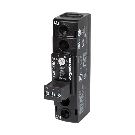
The PMP Series of micro-controller based Single-Phase Proportional Control SSRs are designed to offer precise control of the power delivered to a resistive load in a compact 22.5mm housing, with ratings from 25 up to 90 Amps at 90 to 600 VAC. PMP Series solid state relays can vary the output load power proportionally to an analog control input from 0 to 100%. This can be achieved by two different methods: Phase Angle control and Burst Fire control (with Distributive Zero Cross). The control method to be used can be selected on the unit by means of a selector switch located on top of the SSR. This selector switch also allows to select the type of analog signal to be used at the control input. The available input types are: 0- 5 VDC, 0-10 VDC, and 4-20 mA. PMP Series Proportional SSRs are ideal for lamp dimming and resistive heating control, among other type of applications requiring proportional control.
Industries
Distributors Stock
Part #PMP2490WP
Need more information?
Contact us to request pricing, availability and customization options
Contact UsFeatures
- Single Phase Proportional Controller
- Output ratings up to 90 Amps at 600 VAC
- Selectable operation mode: Phase Angle or Burst Fire control
- Selectable Control Input: 0-5 VDC, 0-10 VDC, 4-20 mA
- 50/60 Hz Adaptive Operational Frequency function
- 4-20 mA input does not require an auxiliary power supply
- LED multifunction status indicator
- Contactor configuration with “Elevator” screw terminals
- cURus, IEC Rated, CE & RoHS Compliant
Specifications
| Description | 25 A | 50 A | 90 A |
| Load Current, General Use UL508 @ 40°C [ARMS] | 25 | 50 | 90 |
| Minimum Load Current [mArms] | 100 | 100 | 150 |
| Maximum 1 Cycle Surge Current (50/60Hz) [Apk] | 286/300 | 716/750 | 1290/1350 |
| Maximum On-State Voltage Drop @ Rated Current [Vrms] | 1.15 | 1.15 | 1.2 |
| Maximum 1/2 Cycle I² t for Fusing (50/60Hz) [A² sec] | 409/375 | 2563/2343 | 8320/7593 |
| Thermal Resistance Junction to Case (Rjc) [°C/W] | 0.49 | 0.27 | 0.2 |
| Maximum Power Dissipation @ Rated Current [W] | 29 | 58 | 104 |
| Recommended Heat Sink for Rated Current @ 40ºC [°C/W] | 2 | 1 | 0.36 |
| Minimum Power Factor (at Maximum load) | 0.7 | 0.7 | 0.7 |
| Phase Angle Control Range [%] | 0 to 100 | 0 to 100 | 0 to 100 |
| Burst Fire Distributive Control Time Base Period | 0 to 20 Cycles | 0 to 20 Cycles | 0 to 20 Cycles |
| Description | Voltage Control | Current Control |
| Valid Input Voltage [VDC] / Current [mA] | 0-10, 0-5 | 4-20 |
| Maximum Allowed Input Voltage [VDC] / Current [mA] | 30 | 35 |
| Maximum Reverse Voltage [VDC] /Current [mA] | -30 | -35 |
| Pick up Voltage [VDC] / Current [mA] | 0.4 | 4.3 |
| Dropout Voltage [VDC] / Current [mA] | 0.1 | 4 |
| Nominal Input Impedance [Ohms] | 28.8k | 230 @ 20 mA |
| Maximum Initialization Time [msec] | 5 Cycles | 5 Cycles |
| Response Time | 1 Cycle | 1 Cycle |
| Description | Parameters |
| Dielectric Strength, Input to Output (50/60Hz) | 4000 Vrms |
| Dielectric Strength, Input/Output to Baseplate (50/60Hz) | 4000 Vrms |
| Minimum Insulation Resistance (@ 500 VDC) | 109 Ohms |
| Maximum Capacitance, Input/Output | 8 pF |
| Ambient Operating Temperature Range | -25 to 70 °C |
| Ambient Storage Temperature Range | -25 to 70 °C |
| Weight (typical) | 2.6 oz (73 g) |
| Housing Material | UL94 V-0 |
| Baseplate Material | Aluminum |
| Hardware Finish | Nickel Plating |
| SSR Mounting Screw Torque Range (lb-in/Nm) | 20-25/2.2-2.8 |
| Humidity per IEC 60068-2-78 | 93% non-condensing |
| LED Input Status Indicator | See Status Chart |
| Overvoltage Category | III |
| Impulse Withstand Voltage According to IEC 60664-1 | 6 kV |
| Adaptive Operational Frequency Function | Yes |