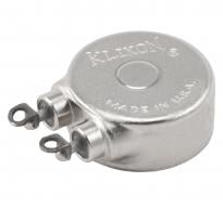
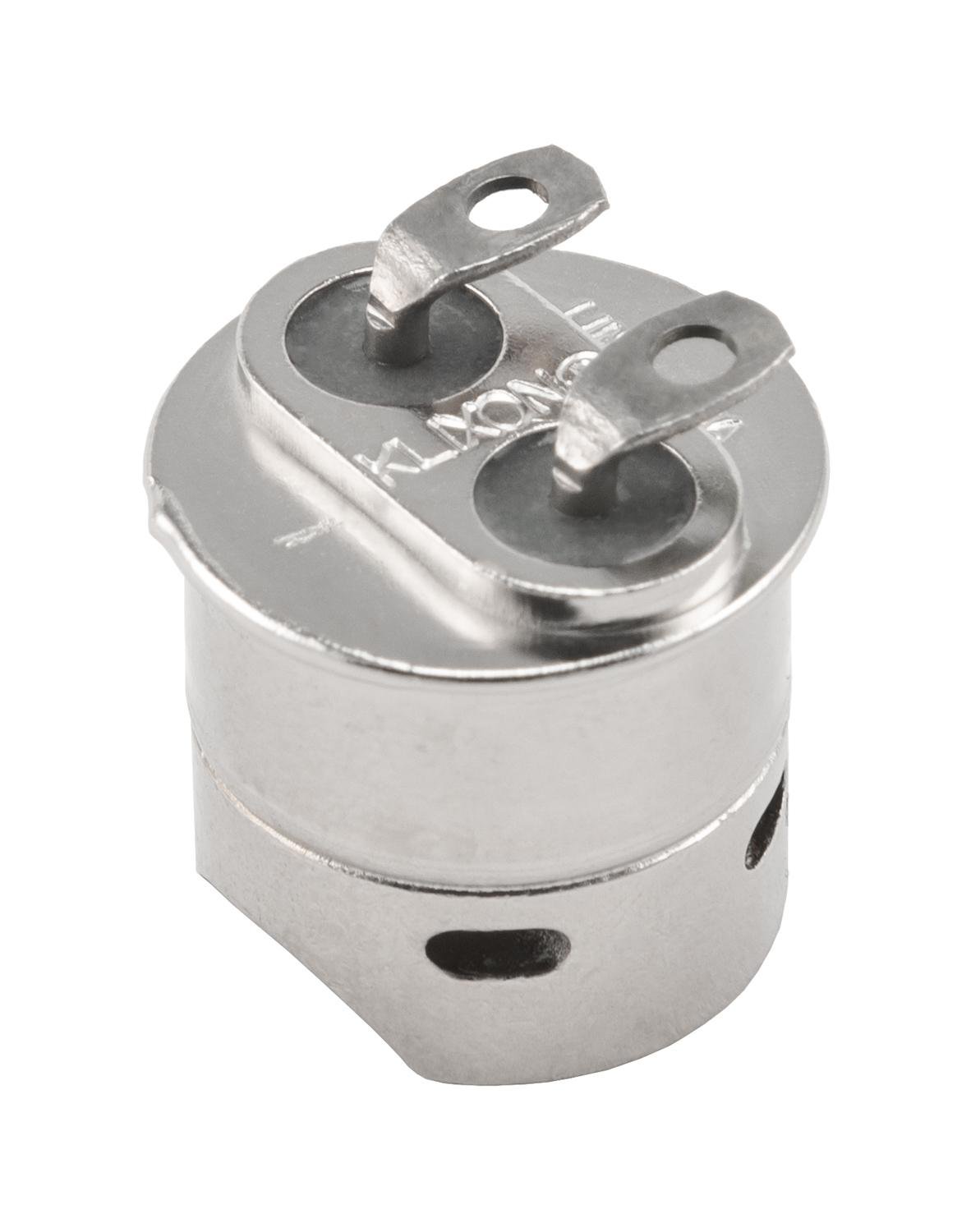
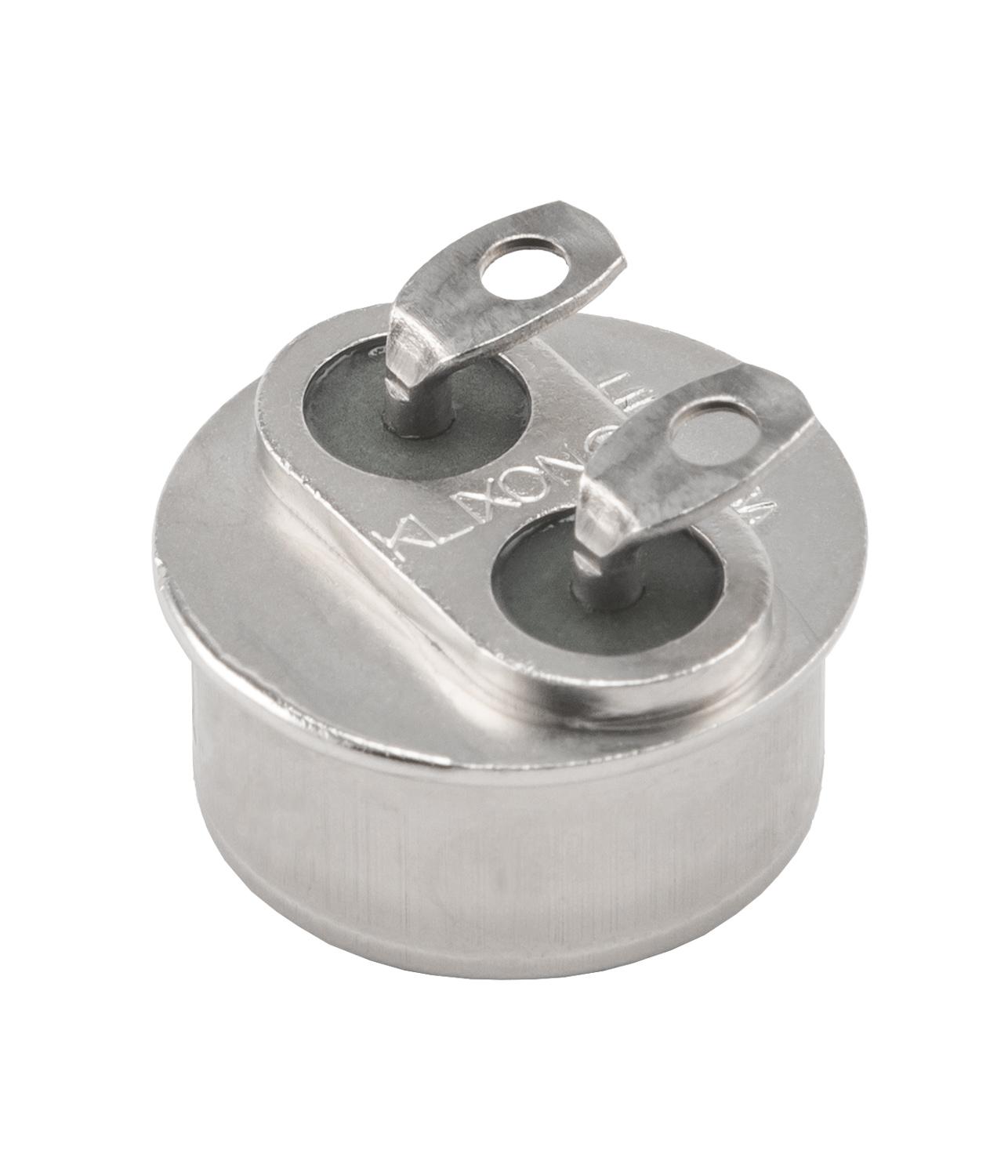
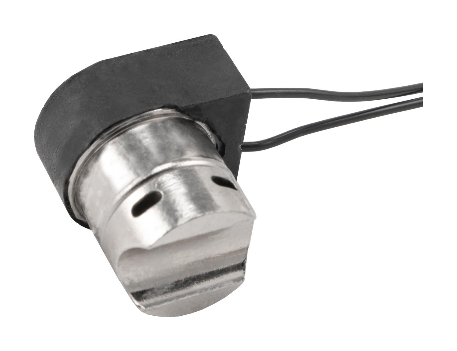
Thermal engineers count on the reliability of Sensata | KLIXON® 11041 thermostats for the demanding environments required on satellites, launch vehicles, and manned space vehicles. For over sixty years, the exceptional vibration and shock resistance enabled thermal control on programs such as GPS, DAWN, James Webb Space Telescope, Space Shuttle, Delta II, Atlas V, and many others. Each 11041 thermostat is vacuum baked and backfilled with inert dry nitrogen atmosphere prior to final sealing to prevent condensation at low temperatures or possible contact contamination at high temperatures. All Sensata space flight thermostats are assembled in a Class 100/ISO 5 cleanroom and undergo Group A Inspection per Table I of NASA S-311-P641. Inspections include pre-cap visual inspection, millipore cleaning, run-in, vibration, particle impact noise detection (PIND) in addition to the standard tests for calibration, creepage, seal, dielectric withstand voltage, insulation resistance, and contact resistance. Each individual thermostat is serialized and shipped with all inspection/screening test data included in the end item data package.
Part #G311P641/05
Contact us to request pricing, availability and customization options
Contact Us| Storage temperature range | -80°F to 550°F (-62.2°C to +287.8°C) Maximum ambient exposure while in the closed position is 200°F above contact closing temperature. |
| Operating temperature range | -55°F to 550°F (-48.3°C to +287.8°C) |
| Contact resistance | 0.025 ohms maximum per MIL-STD-202, Method 307 |
| Dielectric Withstanding Voltage | 1250 VAC, rms, 60 Hz for 1 minute, terminal to case, per MIL-STD-202, Method 301 |
| Vibration | 5-2000 Hz, 20 G, per MIL-STD-202, Method 204, Cond. D (monitored) 5-1000 Hz, 100G, per MIL-STD-202, Method 204, Cond. D (unmonitored) 1000-2000, 50G, per MIL-STD-202, Method 204, Cond. D (unmonitored) |
| Shock | 100G, 6 milliseconds, per MIL-STD-202, Method 213 |
| Seal, Hermetic | 1 X 10⁻⁸ atm cc/sec maximum, per MIL-STD-202, Method 112, Cond. C |
| Salt spray resistance | Per MIL-STD-202, Method 101, Condition B, 5% solution |
| Moisture resistance | Per MIL-STD-202, Method 106 |
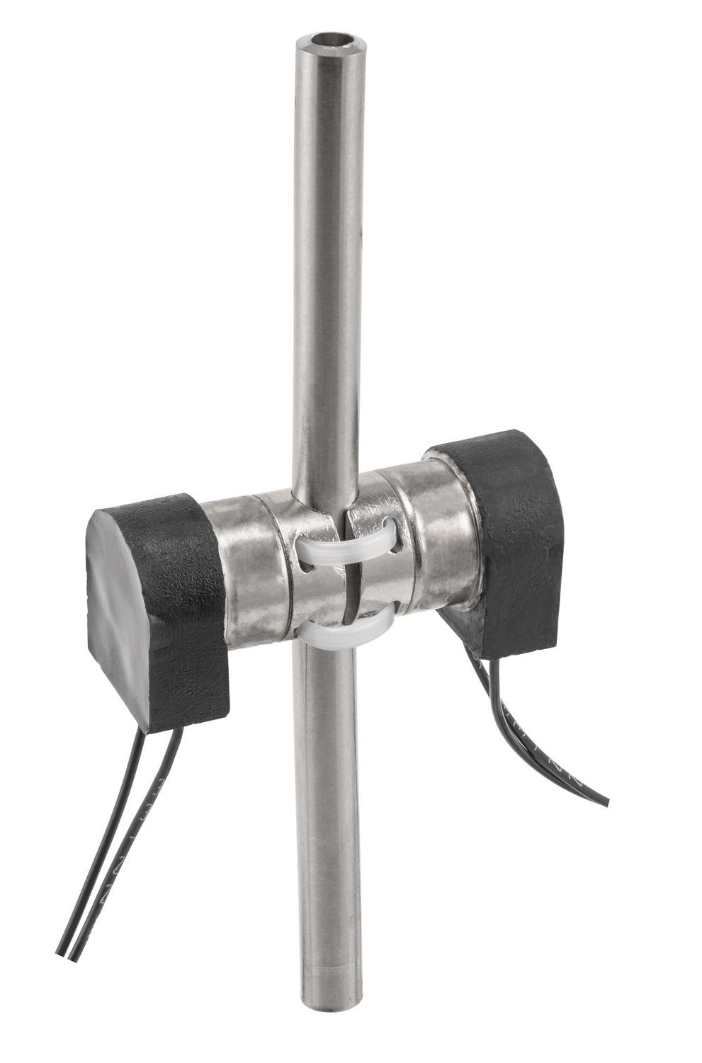
| Weight (avg) | 4.8 grams basic unit; 5.9 grams with bracket |
| Finish | 0.0003 - 0.0004 inches Ni per AMS-QQN-290 over 0.0002 - 0.0003 inches Cu per MIL-C-14550 |
| Wire Leads | Wire Lead Material per Table 4 |
| Qualification | Thermostat design on MIL-PRF-24236/1 Qualified Product Listing |
| Screening |
Switches shall be subjected to 100% Group A screening inspection per S-311-641, Table I, Test Nos. 1-12, with the following details and exceptions:
|
| Operating Temperature Range °F [°C] | Available Differential Range °F [°C] | ||
| Minimum | Standard | Maximum | |
| -55 to -1 [-48.3 to -18.3] |
25 [13.9 ] |
30 [16.7] |
80 [44.4] |
| 0 to 200 [-17.7 to 93.3] |
9 [5] |
20 [11.1] |
80 [40.4] |
| 201 to 300 [93.8 to 148.8] |
20 [11.1] |
30 [16.7] |
80 [44.4] |
| 301 to 450 [149.4 to 232.2] |
30 [16.7] |
40 [22.2] |
80 [44.4 ] |
| 451 to 550 [232.7 to 287.7] |
60 [33.3] |
70 [38.9] |
80 [44.4] |
| Operating Temperature Range °F [°C] | Standard Set Point Tolerance °F [°C] | Special Set Point Tolerance °F [°C] | ||
| Open | Closed | Open | Closed | |
| -55 to -1 [-48.3 to -18.3] |
+/-10 [+/- 5.6] |
+/-8 [+/-4.5] |
+/-8 [+/-4.5] |
+/-6 [+/-4.5] |
| 0 to 200 [-17.7 to 93.3] |
+/-5 [+/-2.8] |
+/-5 [+/-2.8] |
+/-3 [+/-1.7] |
+/-3 [+/-1.7] |
| 201 to 300 [93.8 to 148.8] |
+/-8 [+/-4.5] |
+/-6 [+/-3.3] |
+/-7 [+/-3.9] |
+/-5 [+/-2.8] |
| 301 to 450 [149.4 to 232.2] |
+/-12 [+/-6.7] |
+/-12 [+/-6.7] |
+/-10 [+/-5.6] |
+/-10 [+/-5.6] |
| 451 to 550 [232.7 to 287.7] |
+/-25 [+/-13.9] |
+/-25 [+/-13.9] |
+/-22 [+/-12.2] |
+/-22 [+/-12.2] |
| Contact Material | Contact Rating, Resistive Load (Amperes) | Life Cycles | ||
| 30 VAC/VDC | 125 VAC | 250 VAC | ||
| Fine Silver | 5.0 | 2.0 | 1.0 | 100,000 |
| 5.5 | 3.0 | 1.5 | 50,000 | |
| 6.0 | 4.0 | 2.0 | 25,000 | |
| 6.5 | 5.0 | 2.5 | 10,000 | |
| 7.0 | 6.0 | 3.0 | 5,000 | |
| Gold plated Fine Silver | 12 VDC, 0.5 A, rated to levels as low as 30mVDC, 0.01A |
0.2 A | 0.1 A | 100,000 |
| Wire Lead Ordering Code | Wire Type | Strain Relief Type | Lead Length +/-10% Inch (mm) |
| A | M22759/11-22 (black) | M23053/5, Class 1 | 59.0 (1500) |
| B | M22759/11-22 (black) | STYCAST 2850FT | |
| C | M22759/33-22 (black) | M23053/5, Class 1 | |
| D | M22759/33-22 (black) | STYCAST 2850FT | |
| E | M22759/43-22 (black) | M23053/5, Class 1 | |
| F | M22759/43-22 (black) | STYCAST 2850FT |
| Tube Mount Adapter Size Ordering Code | Tube Mount Adapter Diameter Inch (mm) |
| 1 | .256 +.010/-.000 (6.50 +.25/-.000) |
| 2 | .381 +.010/-.000 (9.68 +.25/-.000) |
| Tube Mount Adpater Orientation Ordering Code | Tube Mount Adapter Mounting Angle (+/-10°) |
| 1 | 0° (Terminal Orientation Parallel To The Tube Direction) |
| 2 | 45° |
| 3 | 90° |
| 4 | 135° |