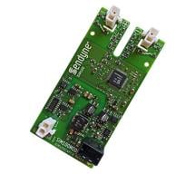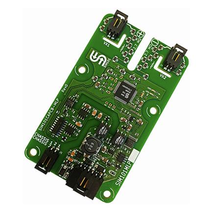
SIM100MLP Module
Insulation Monitoring Devices
The Sensata | Sendyne SIM100MLP is the first high voltage isolation monitoring / insulation monitoring / IMD device for Electric Vehicles (EV/HEVs) and charging stations capable of operating correctly even when the battery is active, and experiencing large voltage variations. The SIM100MLP continuously monitors the isolation resistance between a vehicle’s IT (Isolated Terra) power system and chassis for deterioration of isolation and potentially dangerous levels of leakage current. The module detects not only resistive leakages but also capacitively stored energy that could be harmful to human operators.
Due to a proprietary, patented and patent pending advanced algorithm, the module is capable of detecting all sources of leakage, including multiple, simultaneous symmetrical and asymmetrical faults, as well as resistive paths between the chassis and points in the battery with the same potential as the chassis. In the case of an isolation fault, the unit identifies the position of the fault in relation to the battery’s terminals. Battery-connected VX1 (Vp) and VX2 (Vn) voltage inputs can measure ±1.1 kV (max, see ordering options for other ranges) in reference to Chassis (0 V). Communications are achieved via an isolated CAN 2.0B interface and the unit operates over a wide temperature range of –40 °C to +105 °C/+125 °C without connectors.
Industries
Distributors Stock
Part #SIM100MLP
Need more information?
Contact us to request pricing, availability and customization options
Contact UsFeatures
- Measures voltage of each battery terminal with refernce to chassis
- Reports battery voltage
- Reports accurate estimates of the isolation status while the battery is having large voltage variations
- When the battery is not connected or if the battery voltage drops below 15 V, the parallel combination of the two reported isolation resistances (for the high and low sides) is still accurate, as well as the sum total of the reported high and low capacitances
- Measures and reports modeled leakage resistances per model adapted by the safety standards ISO6469-1, FMVSS §571.305 and others
- Reports calculated isolation resistance in Ω/V per requirements of the safety standards
- Measures and reports the value of capacitance from each battery terminal to chassis
- Calculates and reports the energy stored by the total capacitance between the battery and chassis
- Reports uncertainty for all measured and calculated values
- Continuously monitors connections of the voltage sense lines to the battery terminals; reports inadequate connections
- Continuously monitors connection of the unit to chassis; reports inadequate connection
- Provides high immunity to common-mode noise that can be present on the battery terminals
- Provides nonvolatile storage for the value of the maximum (design) voltage of the battery (used in calculations of the isolation resistance and stored energy). If the actual observed battery voltage is higher than the set maximum voltage, the higher value is used in the calculations of the isolation resistance and stored energy
- Provides nonvolatile storage for calibration of the voltage measurements and other parameters; all reported measurements have their respective calibration parameters applied automatically
- Provides built-in galvanically isolated and intrinsically leakage-safe excitation source
- A single CAN message provides sufficient information for determination of the safety status of the system
- Initializes in under 6 seconds
- Fast detection of a rapid change in insulation resistance: The SIM100 detects an insulation value change in less than 5 secs
- Warning and Fault alerts provided in the STATUS byte for low insulation resistance values
Specifications
| Parameter | Value |
| Power supply | +4.8 to +53 V (variable, accommodating +5 V to +48 V power supplies) |
| Interface | CAN 2.0B isolated, 120 Ω termination resistor (optional) |
| Maximum Operational Voltage | +/- 1000 V |
| Component Ratings | Automotive |
| Module operating temperature range | -40 °C to +125 °C for electronics (-40 °C to +105 °C with connectors) |
| Part Number | Voltage |
| SIM100MLP-XXX | SIM100MLP module. See table below for XXX options. |
Ordering Options (XXX)
| CAN bus | Voltage | Connectors & CAN Termination |
| A = 500kbit/s B = 250kbit/s |
K = 1000 V | A = Terminated B = Not terminated |
| SIM100 System Requirement |
SIM100MLP-xxx |
Note |
|
Minimum HV System Y-Capacitance (Chassis to each of HV + and HV -) |
100 nF |
Y-Capacitance must be present for the proper functioning of the SIM100 family |
|
Minimum HV System Voltage (HV + and HV -) |
15V | SIM100 is optimized for operation when the HV system is active |
|
Allowable System Insulation (Chassis to each of HV + and HV -) |
2.72 Megaohm | SIM100 couples to HV network via series resistors and represents an intrinsic load between the HV system and chassis |